

Products
The mechanical and electrical needs of a project determine the type of flexible circuit used. When selecting a flexible circuit, weigh the advantages of the circuit against the total installed cost, including inspection, interconnection, tooling and testing. PFC experts help guide clients on the best flex circuit to maximize efficiency and minimize costs.
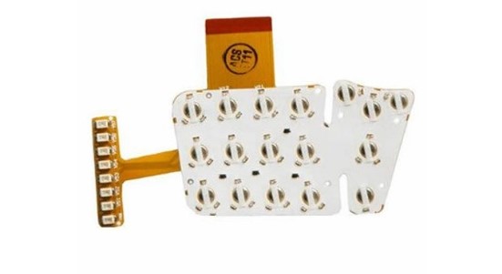
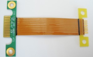
Single Sided
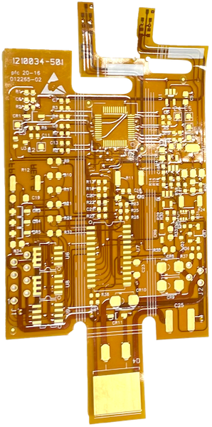
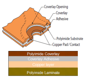
Single-sided flex circuits are the most basic type of flexible circuits. They have one layer of copper laminated between polyimide dielectrics. We chemically etch the copper layer to produce a circuit pattern specific to design requirements. Stiffeners, pins, connectors, and components, are optional. Single-sided flex circuits are durable across applications and are excellent for installations in with small spaces.
- Complete assembly
- SMT and/or through- hole
- Simplified design and manufacturing
- Dynamic flexing applications
- Minimized interconnect errors
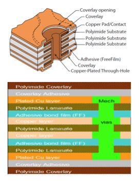
Double sided
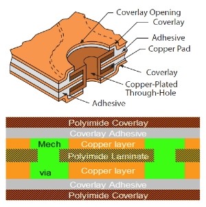
Double-sided circuits have two layers of copper laminated between polyimide dielectrics. In most cases, the two layers of copper are electrically connected by drilling small holes through the copper circuits and the separating dielectric. The holes are then plated with copper to make a connection between them. The slideshow below shows the artwork required for each layer of the circuit build.
- Wider circuit design parameters
- Access to circuit traces from both sides of the flex configuration
- Reduced assembly costs due to minimized interconnect errors
- Dynamic flexing ability
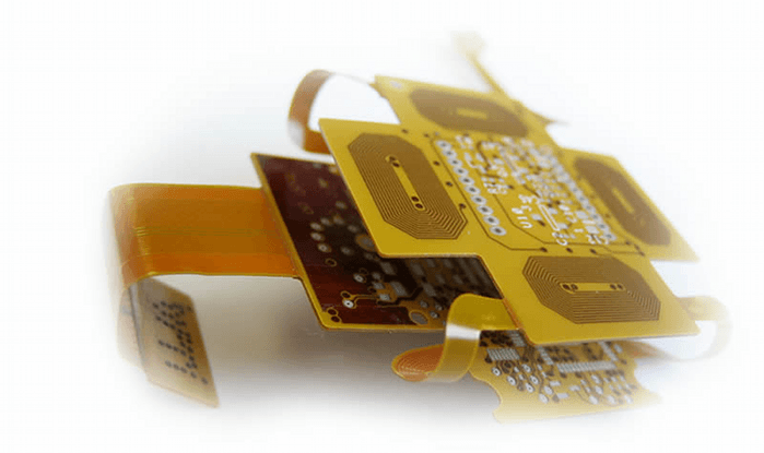
Multi-layer
Multi-layer flexible circuits combine several single-sided or double-sided circuits with complex interconnections, shielding and/or surface mounted technologies in a multilayer design. The number of conductor layers designed into multi-layer flex circuits are limitless. The package size, layer count vs. flexibility is considered during the design layout for ease of installation. Below is a slideshow of a four layer flex circuit for a digital camera application.
- Up to 14 layers
- Bare flex or complete assembly
- SMT and/or through- hole
- Provides superior signal integrity
- More signals can be routed in the circuit
- Offers localized areas for stiffeners and components to be added
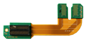
Rigid Flex
Rigid flex circuits combine the benefits of rigid boards and flexible circuits integrated into one circuit. The two-in-one circuit is interconnected through plated through holes. Rigid flex circuits provide higher component density and better quality control. The slideshow below shows an eight layer rigid flex circuit used for a medical device. Four layers are rigid and four layers are flexible. There are connectors required on two different sides of the circuit, which is carrying signals and power.
- Improved connectivity and signal integrity
- Allows for placement of fine-pitch components and small components
- Meets double-sided assembly requirements
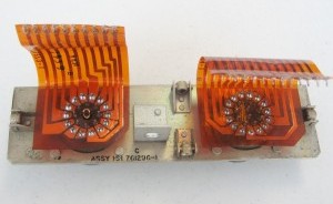
Sculptured flex
Sculpted flexible circuits have sculpted pins, which are made as a through-hole connector. Sculptured terminal pins are built-in and extended beyond the boundary of the polyimide base material. These pins are plugged into a series of holes in a PCB and then soldered. This circuit design, is also able to be soldered to a series of surface mount pads. Sculpted flex circuits are often chosen to eliminate the need and cost of a ZIF connector.
- Built-in contacts eliminate the need to purchase connectors
- Integrated design reduces assembly labor costs
- Elimination of connector components saves weight and space and increases flexibility
- Excellent reliability and performance
PFC High Speed Data Links
PFC has created the PFC High Speed Data Link Flexible Circuits product line, in collaboration with Samtec. The PFC Data Link is a direct cross to the Samtec Data Link product line, a leader in transmitting and receiving digital information. Our strategic partnership with Samtec has provided customers with improved interconnectivity for PFC and expert flex circuit assembly for Samtec.
Below are the available PFC High Speed Data Link Flexible Circuit drawing packages and product descriptions. The PFC Data Link drawings include:
- A bill of materials
- Test parameters
- Electrical requirements
- Specific part number listing
- Dimensions
- Material stack
PFC-HFEM2-DP
PFC Flex Circuit Assembly, 2 layers, IPC 6013 class 2, RoHS compliant
Samtec QXE High Speed Ground Plane Socket interface – 14, 20, 28, 40, 42 and 60 positions
Differential pairs, 100 Ohms, +/-10% impedance control, microstrip design
The standard lengths are 3, 5 and 10 inches (custom lengths available – contact PFC)
Samtec promotes these protocols to be supported with the QSE/QTE connector system:
XAUI, PCI Express®, SATA, MGT (Rocket I/O), InfiniBand™
Download the PFC-HFEM2-Dp Data Link drawing package
PFC-HFEM2-SE
PFC Flex Circuit Assembly, 3 layers, IPC 6013 class 2, RoHS compliant
Samtec QSE and QTE High Speed Ground Plane Socket interface – 14, 28, and 42 positions
The standard lengths are 3, 5 and 10 inches (custom lengths available – contact PFC)
Differential pairs, 100 Ohms, +/-10% impedance control
Samtec promotes these protocols to be supported with the QSE/QTE connector system:
XAUI, PCI Express®, SATA, MGT (Rocket I/O), InfiniBand™
Download the PFC-HFEM2-SE Data Link drawing package
PFC-HFEM-DP
PFC Flex Circuit Assembly, 3 layers, IPC 6013 class 2, RoHS compliant
Differential pairs, 100 Ohms, +/-10% impedance control
Samtec QSE and QTE High Speed Ground Plane Socket interface – 14, 28, and 42 positions
Standard lengths are 3, 5 and 10 inches (custom lengths available – contact PFC)
Available with and without mounting holes
Samtec promotes these protocols to be supported with the QSE/QTE connector system:
XAUI, PCI Express®, SATA, MGT (Rocket I/O), InfiniBand™
Download the PFC-HFEM-DP Data Link drawing package
PFC-HFEM-SE
PFC Flex Circuit Assembly, 3 layers, IPC 6013 class 2, RoHS compliant
Samtec QSE and QTE High Speed Ground Plane Socket interface – 14, 28, and 42 positions
The standard lengths are 3, 5 and 10 inches (custom lengths available – contact PFC)
Differential pairs, 100 Ohms, +/-10% impedance control
Samtec promotes these protocols to be supported with the QSE/QTE connector system:
XAUI, PCI Express®, SATA, MGT (Rocket I/O), InfiniBand™
Download the PFC-HFEM-SE Data Link drawing package
PFC-HFHM-DP
PFC Flex Circuit Assembly, 3 layers, IPC 6013 class 2, RoHS compliant
Samtec QSE and QTE High Speed Ground Plane Socket interface – 14, 28, and 42 positions
The standard lengths are 3, 5 and 10 inches (custom lengths available – contact PFC)
Differential pairs, 100 Ohms, +/-10% impedance control
Samtec promotes these protocols to be supported with the QSE/QTE connector system:
XAUI, PCI Express®, SATA, MGT (Rocket I/O), InfiniBand™
Download the PFC-HFHM-DP Data Link drawing package
PFC-HFHM2-DP
PFC Flex Circuit sssembly, 3 layers, IPC 6013 class 2, RoHS compliant
Samtec QSE and QTE High Speed Ground Plane Socket interface – 14, 28, and 42 positions
The standard lengths are 3, 5 and 10 inches (custom lengths available – contact PFC)
Differential pairs, 100 Ohms, +/-10% impedance control
Samtec promotes these protocols to be supported with the QSE/QTE connector system:
XAUI, PCI Express®, SATA, MGT (Rocket I/O), InfiniBand™